
📄 Exam Questions & Readable Text Transcript
Full OCR-extracted text of questions, syllabus codes, and exam instructions.
Extracted Content: 6047q2 Specimen paper
Page 1
Extracted Text
nentZIMBABWE SCHOOL EXAMINATIONS COUNCIL
General Certificate of Education Advanced Level
TECHNICAL GRAPHICS AND DESIGN 6047/2
PAPER 2 Mechanical and Building Drawing
SPECIMEN PAPER 3 hours 10 minutes
Additional materials:
A2 Drawing paper (2 sheets)
TIME 3 hours 10 minutes
INSTRUCTIONS TO CANDIDATES
Print your name, Centre number and candidate number at the bottom right-hand corer of your
answer sheet.
Y ou should spend the first ten minutes reading the whole question paper before attempting the
questions.
There are two questions from building drawing and two questions from mechanical drawing.
Answer any one question on the separate drawing paper provided.
Short concise notes and small auxiliary sketches may be presented to clarify any design features.
Measurements not given are left to your own discretion. Work out all your answers in SI units.
If you use more than one sheet of paper, fasten the sheets together.
INFORMATION FOR CANDIDATES
Marks are given in brackets [ ] at the end of each question or part question.
The diagrams are not necessarily drawn to scale.
All dimensions are in millimetres unless otherwise stated.
Y ou are reminded of the need for good English and clear presentation in your answers.
This question paper consists of 11 printed pages, 1 blank page.
Copyright: Zimbabwe School Examinations Council, Specimen paper.
ZIMSEC Specimen paper
[Turn over
---
Page 2
Extracted Text
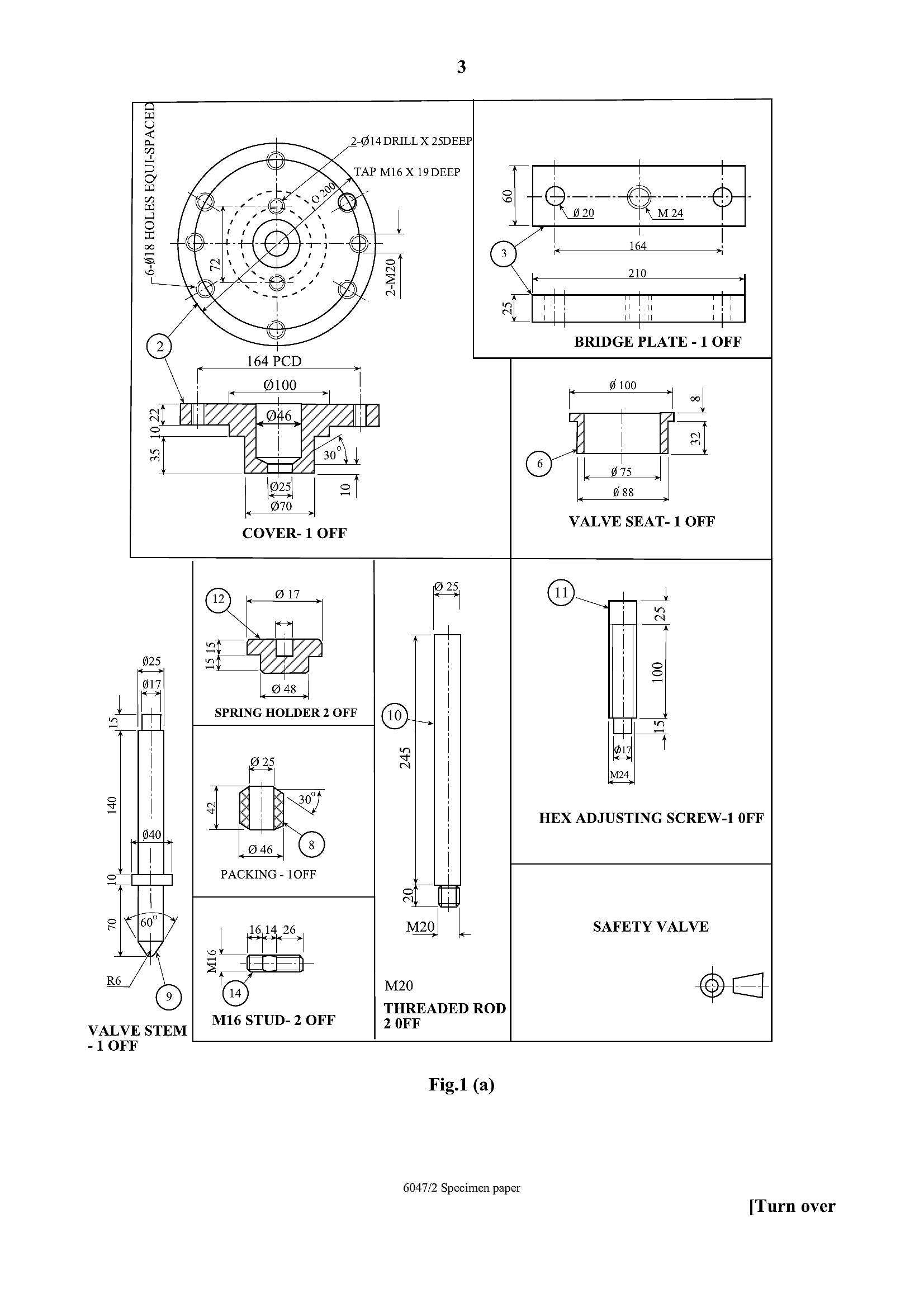
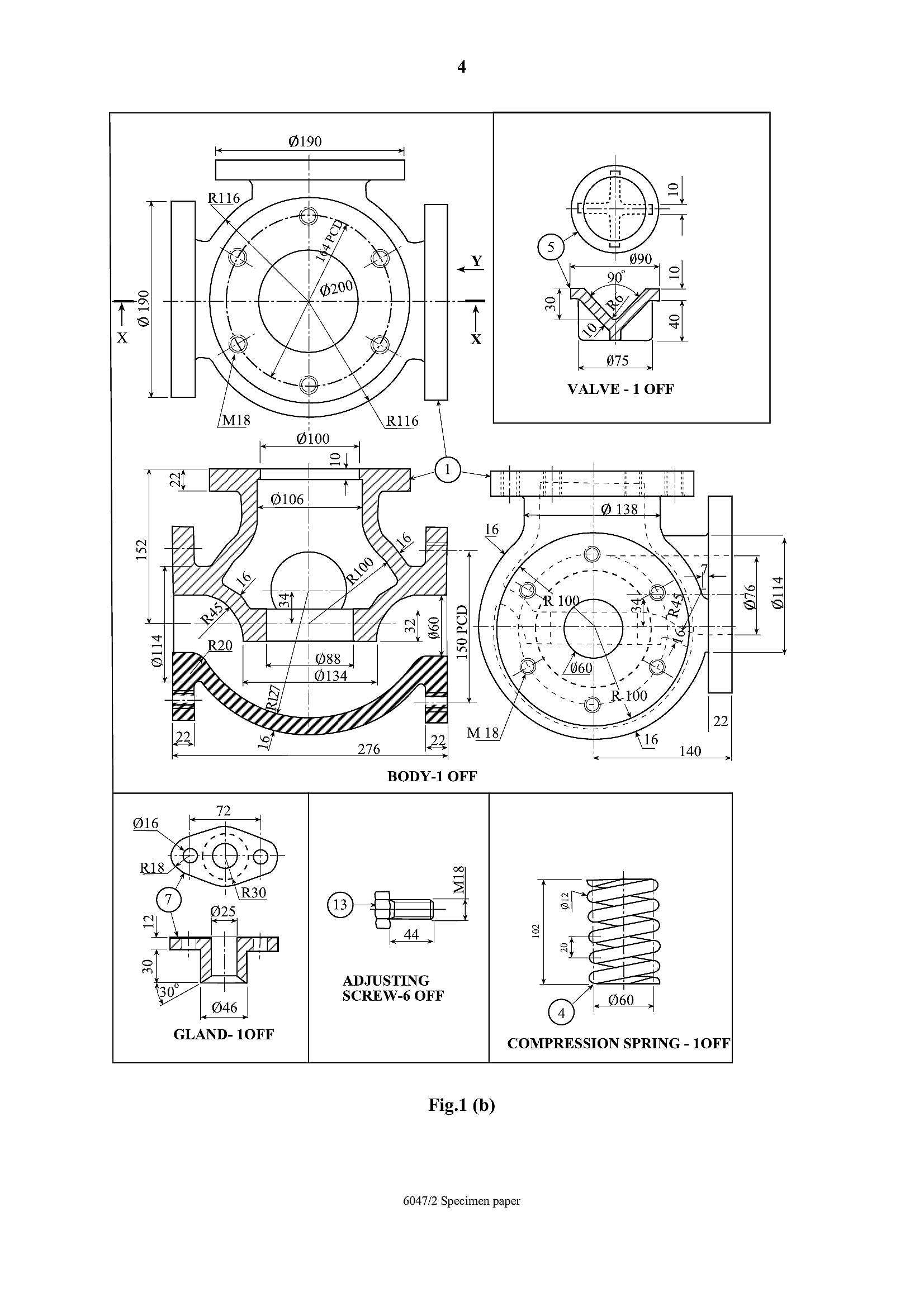
Question 1The components of a Safety Valve are shown in third angle projection.
Method of Assembly
Valve (5) is slid into the valve seat (6) from the flange side. The sub-assembly
is inserted into the body (1) such that the valve seat flange is in contact with the body.
The valve stem (9) is lowered into the body until the rounded end sits on the valve.
Next, the packing (8) is inserted into the cover (2). The gland (7) is then used to
keep the packing in place. The gland is held in position by two M16 studs (14). The
sub-assembly is slid over the valve stem, such that the cover is fastened to the body by
6 adjusting screws (13). 2 M20 threaded rods (10) are then screwed into the cover.
Spring holders (12) are placed on either end of the spring (4). The sub-assembly
is placed such that the dog end of the stem end gets into the lower spring holder. The
bridge plate (3) is pushed over the threaded rod, and then the hexagon adjusting screw (11)
is screwed into the bridge plate so that its dog end gets into the upper spring holder.
To complete this assembly the following design features are required:
@ a method of sealing between the cover and the body, [2]
(ii) ameans of locking the adjusting screw in a desired position, [4]
(iii) | amethod of hand operating the adjusting screw, [4]
(iv) | ameans of keeping the plate in position. [2]
Draw to a scale of 1:2 either in first or third angle projection, the following
views of the complete assembly:
(a) a sectional elevation along the cutting plane X-X, as shown on the body, [52]
(b) in projection with view (a), a plan, [17]
(c) an outside end view in the direction of arrow Y. [19]
NB. Do not show hidden details.
Chamfers, small radii and dimensions not shown are left to your discretion.
6047/2 Specimen paper
---
Page 3
Extracted Text
6-018 HOLES EQUI-SPACEDqe
BRIDGE PLATE - 1 OFF
6 100
az
~ “ee aac
3510.22,
Ky
iS
lef
n
¥
; | v7
|g25| S 988
070
COVER-1 OFF VALVE SEAT- 1 OFF
es | Ol
nw
nN
100
|
|
2 |
i” @48 |
SPRING HOLDER 2 OFF |
a |
(O17)
wo
t+ ' —
nN
M24
_+(L5
HEX ADJUSTING SCREW-1 OFF
ch
a0
16,14, 26 m29| L SAFETY VALVE
2S J
®)
M20 (6)
THREADED ROD
M16 STUD- 2 OFF 20FF
VALVE STEM
-1 OFF
Fig.1 (a)
6047/2 Specimen paper
[Turn over
---
Page 4
Extracted Text
114150 PCD
GLAND- 10FF
44
x»
ADJUSTING
SCREW-6 OFF
COMPRESSION SPRING - 10FF
Fig.1 (b)
6047/2 Specimen paper
---
Page 5
Extracted Text
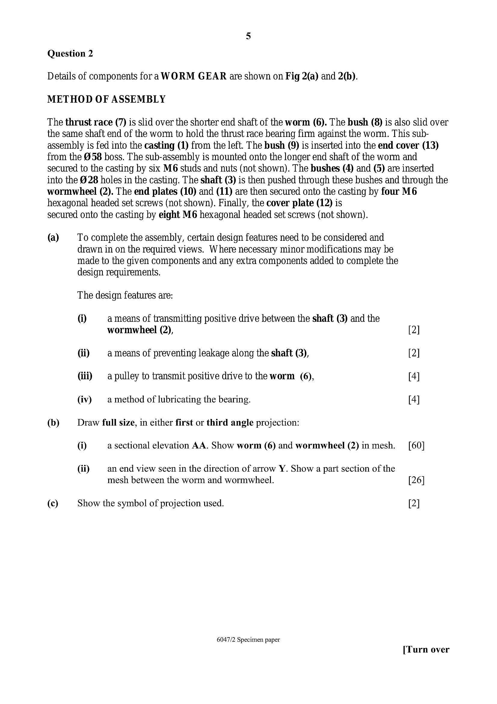
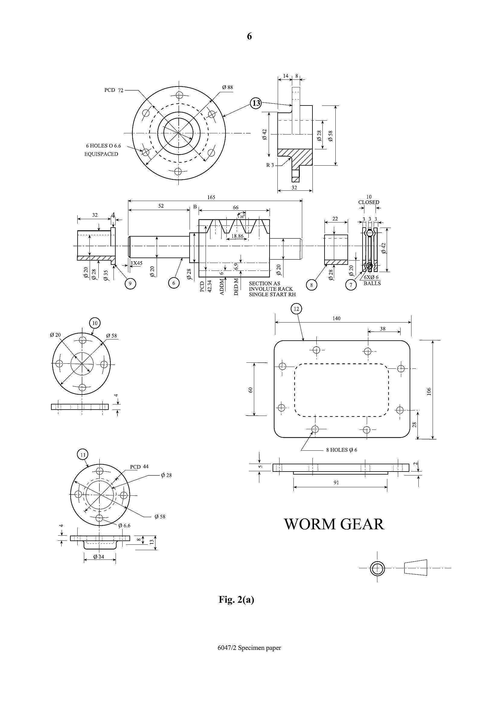
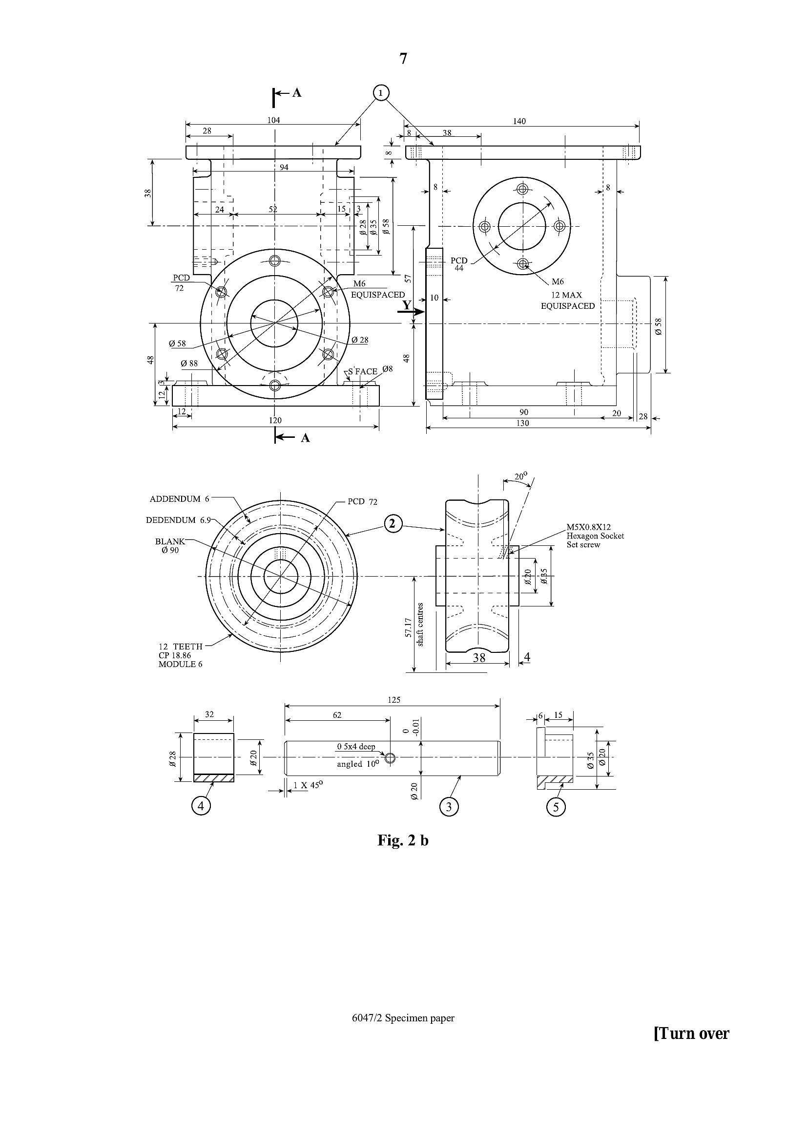
Question 2 Details of components fora WORM GEAR are shown on Fig 2(a) and 2(b). METHOD OF ASSEMBLYThe thrust race (7) is slid over the shorter end shaft of the worm (6). The bush (8) is also slid over
the same shaft end of the worm to hold the thrust race bearing firm against the worm. This sub-
assembly is fed into the casting (1) from the left. The bush (9) is inserted into the end cover (13)
from the @58 boss. The sub-assembly is mounted onto the longer end shaft of the worm and
secured to the casting by six M6 studs and nuts (not shown). The bushes (4) and (5) are inserted
into the @ 28 holes in the casting. The shaft (3) is then pushed through these bushes and through the
wormwheel (2). The end plates (10) and (11) are then secured onto the casting by four M6
hexagonal headed set screws (not shown). Finally, the cover plate (12) is
secured onto the casting by eight M6 hexagonal headed set screws (not shown).
(a) Tocomplete the assembly, certain design features need to be considered and
drawn in on the required views. Where necessary minor modifications may be
made to the given components and any extra components added to complete the
design requirements.
The design features are:
@ a means of transmitting positive drive between the shaft (3) and the
wormwheel (2), [2]
(ii) a means of preventing leakage along the shaft (3), [2]
(iii) a pulley to transmit positive drive to the worm (6), [4]
(iv) | amethod of lubricating the bearing. [4]
(b) Draw full size, in either first or third angle projection:
@ a sectional elevation AA. Show worm (6) and wormwheel (2) in mesh. [60]
(ii) an end view seen in the direction of arrow Y. Show a part section of the
mesh between the worm and wormwheel. [26]
(c) Show the symbol of projection used. [2]
6047/2 Specimen paper
[Turn over
---
Page 6
Extracted Text
PCD 726 HOLES 0 6.6
EQUISPACED
WORM GEAR
G34
Fig. 2(a)
6047/2 Specimen paper
---
Page 7
Extracted Text
140T T ?
oh le
M6 i
12MAX | .
EQUISPACED : i
H 90 20 slog
130 *
20°
/
ADDENDUM 6
DEDENDUM 6.9
MS5X0.8X12
Hexagon Socket
BLANK Set screw
| fe |
ae | yap
g
12 TEETH a ae
CP 18.86
MODULE 6 38 | |4
125 .
‘ 32 ' le 62 4 51S,
o ¢ A
I Z Too ‘
« a_i Csetden| t tL ule
S ® angled 10° 3|®
| E2zzd :
[2x4 g “I-A y
@) ° ©
Fig. 2 b
6047/2 Specimen paper
O58
[Turn over
---
Page 8
Extracted Text
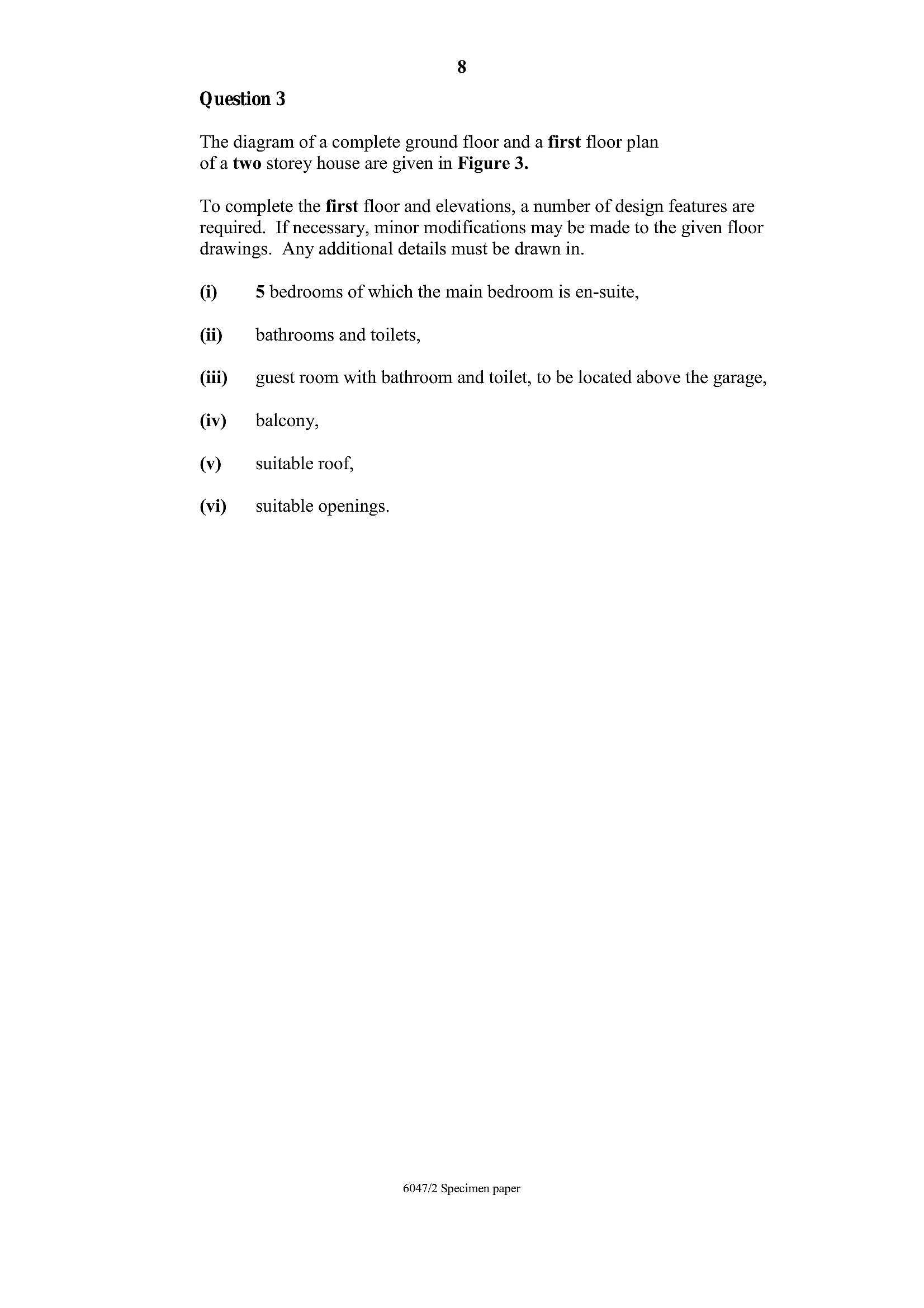
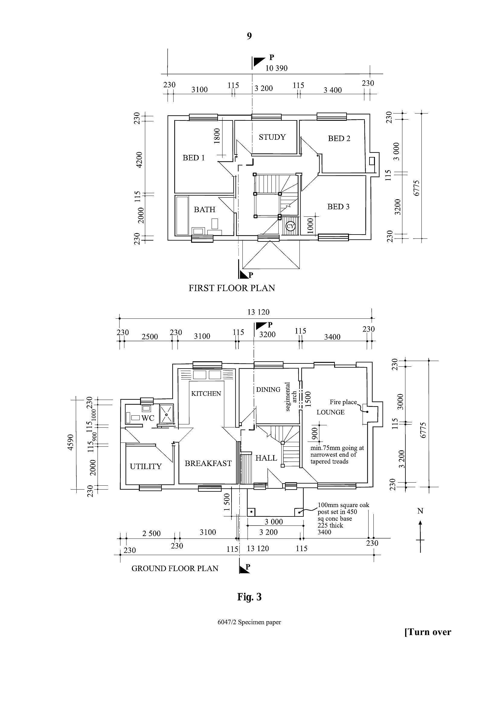
Question 3The diagram of a complete ground floor and a first floor plan
of a two storey house are given in Figure 3.
To complete the first floor and elevations, a number of design features are
required. If necessary, minor modifications may be made to the given floor
drawings. Any additional details must be drawn in.
@ 5 bedrooms of which the main bedroom is en-suite,
(ii) ~—s bathrooms and toilets,
(iii) | guest room with bathroom and toilet, to be located above the garage,
(iv) balcony,
(v) suitable roof,
(vi) suitable openings.
6047/2 Specimen paper
---
Page 9
Extracted Text
4590P
‘i 0 390
230
wat 3100 115 3.200 M5 3400
T
+
2 —= act
$
x BED 2
2°
Ss
S BEDI = : S
+
woe
_ w
, BED 3 S
= BATH a
: Ze E
coh = °
ee (Lee toes} gt |
Ke
FIRST FLOOR PLAN
13 120
115 230
fp 2500 P3100 Hf 3200 P3400 in
= = at
7 } | DINING g ll
o KITCHEN | g 3] = 3
Q 2 s q na} Fire place. | = s
8 Nowe \/ | * 1) LOUNGE
= ZN :
4 — ee: tj s as ra
“3 S &
& Es S
4 min.75mm going at
HALL narrowest end of s
s UTILITY BREAKFAST | tapered treads Q
a
2°
a E t T — + a ft t
“ s
0 100mm square oak
7 ° l [ “1 post set in 450 N
i sq conc base
3.000 225 thick
2 500 3100 3 200 3400
+ +f al { 330
4230 230 115] 13 120 115
GROUND FLOOR PLAN Ng
Fig. 3
6047/2 Specimen paper
[Turn over
---
Page 10
Extracted Text
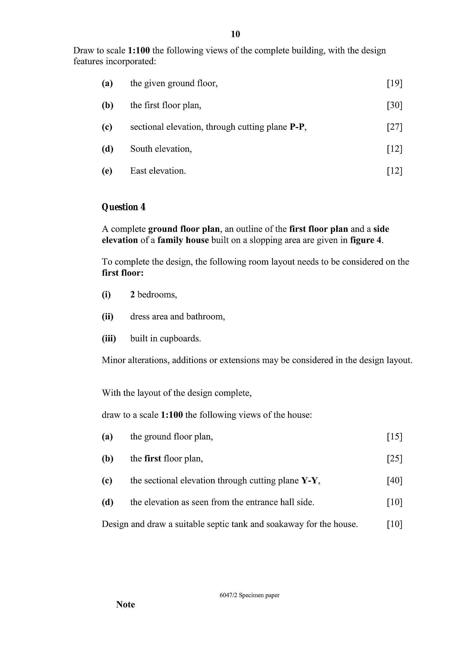
10Draw to scale 1:100 the following views of the complete building, with the design
features incorporated:
(a) the given ground floor, [19
(b) the first floor plan, [30
(c) sectional elevation, through cutting plane P-P, [27
(d) South elevation, [12
(e) East elevation. [12
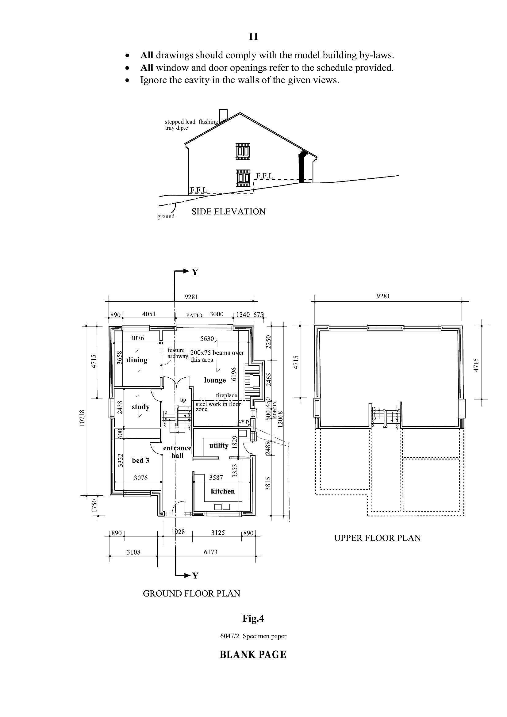
Question 4
A complete ground floor plan, an outline of the first floor plan and a side
elevation of a family house built on a slopping area are given in figure 4.
To complete the design, the following room layout needs to be considered on the
first floor:
0) 2 bedrooms,
(ii) dress area and bathroom,
(iii) —_ built in cupboards.
Minor alterations, additions or extensions may be considered in the design layout.
With the layout of the design complete,
draw to a scale 1:100 the following views of the house:
(a) the ground floor plan, [15
(b) the first floor plan, [25
(c) the sectional elevation through cutting plane Y-Y, [40
(d) the elevation as seen from the entrance hall side. [10
Design and draw a suitable septic tank and soakaway for the house. [10
6047/2 Specimen paper
Note
---
Page 11
Extracted Text
11e All drawings should comply with the model building by-laws.
e All window and door openings refer to the schedule provided.
e Ignore the cavity in the walls of the given views.
stepped lead flashing
tray d.p.c 2
4715
10718
od
F.
—
SIDE ELEVATION
ground
Y
+ 9281 LE 4 9281 i
_}390] 4051 |_patio 3000 1340
Tt ot 1 4
F 7
3076 5630,
eI " feature 200x75 beams over
<<] dining ai ¥ this area 5 2
& = +
nae lounge ©| E 3
=
7 -— fteplace| Ee +
8 say ag soa ae
| : fi] ge
| alae vel) T'S
+ 7 ~
‘li ee oi
entrance] utility = a
all oN a
B
! a
3587 | 4 |
ze |
kitchen o
Ly |
: +4
1890 | 1p28 3125 94
804 _ ann UPPER FLOOR PLAN
3108 6173 I
Y
GROUND FLOOR PLAN
Fig.4
6047/2 Specimen paper
BLANK PAGE
---
Page 12
Extracted Text
126047/2 Specimen paper
---