📄 Exam Questions & Readable Text Transcript
Full OCR-extracted text of questions, syllabus codes, and exam instructions.
Extracted Content: 6047q01
Page 1
Extracted Text
ZIMBABWE SCHOOL EXAMINATIONS COUNCILGeneral Certificate of Education Advanced Level
TECHNICAL GRAPHICS AND DESIGN 6047/1
PAPER 1 Applied Geometry
SPECIMEN PAPER 3 hours
Additional materials: A2 Drawing paper (4 sheets)
Standard Drawing Equipment
TIME 3 hours
INSTRUCTIONS TO CANDIDATES
Print your name, centre number and candidate number at the bottom right-hand comer of
every sheet of paper you use.
Answer all questions in Section A and any three questions in Section B.
Write or draw your answers on the separate drawing paper provided.
Work out all your answers in SI units. Use both sides of the drawing paper.
All solutions are to be drawn full size unless a contrary instruction is given. Construction
lines must be shown clearly.
Measurements not given are left to your own discretion.
If you use more than one sheet of paper, fasten the sheets together.
INFORMATION FOR CANDIDATES
The number of marks is given in brackets [ ] at the end of each question or part question.
[he diagrams are not necessarily drawn to scale.
All dimensions are in millimetres unless otherwise stated.
Y ou are reminded of the need for clear presentation in your answers.
This question paper consists of 10 printed pages and 2 blank pages.
Copyright: Zimbabwe School Examinations Council, Specimen paper.
ZIMSEC Specimen paper [Turn over
---
Page 2
Extracted Text
1.(a)
6b)
SECTION A [40 Marks]
Answer alll questions.
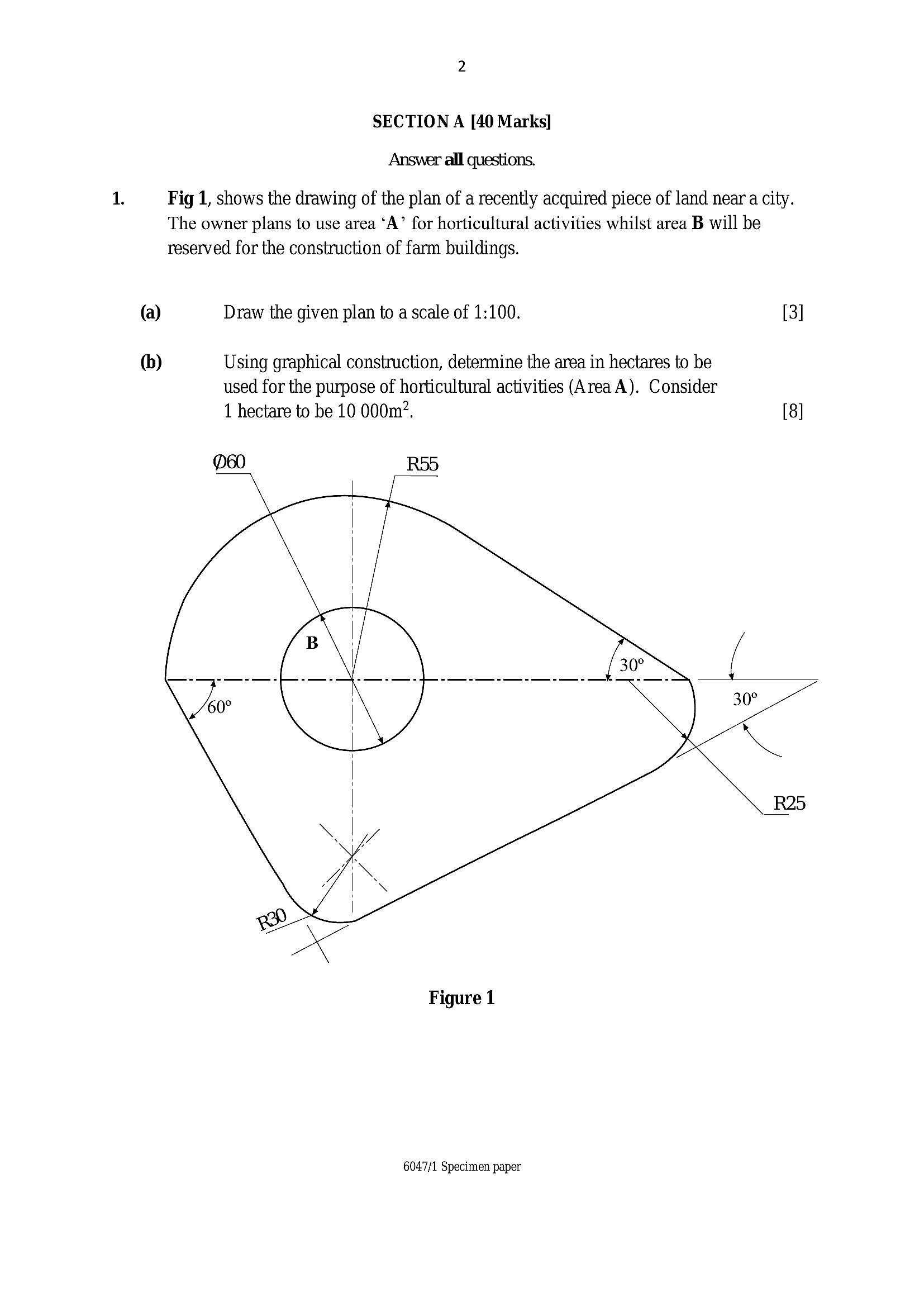
Fig 1, shows the drawing of the plan of a recently acquired piece of land near a city.
The owner plans to use area ‘A’ for horticultural activities whilst area B will be
reserved for the construction of farm buildings.
Draw the given plan to a scale of 1:100. [3]
Using graphical construction, determine the area in hectares to be
used for the purpose of horticultural activities (Area A). Consider
1 hectare to be 10 000m2. [8]
@60 R55
Figure 1
6047/1 Specimen paper
---
Page 3
Extracted Text
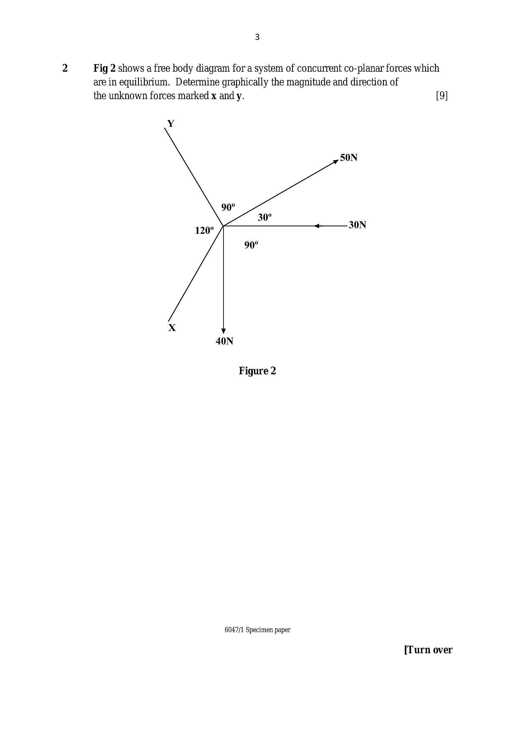
2 Fig 2 shows a free body diagram for a system of concurrent co-planar forces which are in equilibrium. Determine graphically the magnitude and direction of the unknown forces marked x and y. [9]Y
30N
v
40N
Figure 2
6047/1 Specimen paper
[Turn over
---
Page 4
Extracted Text
3(a)
6b)
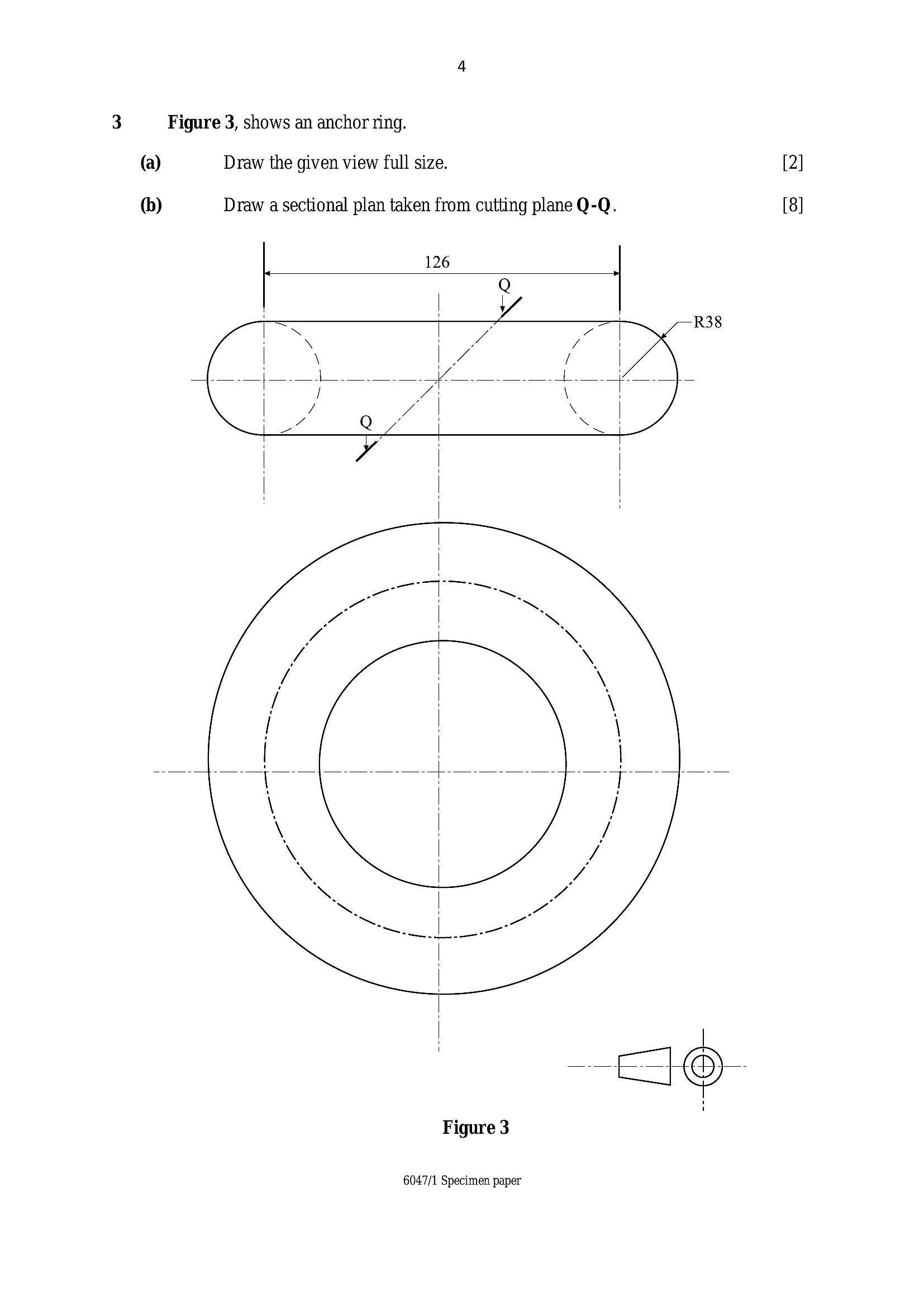
Figure 3, shows an anchor ring.
Draw the given view full size.
Draw a sectional plan taken from cutting plane Q-Q.
126
Figure 3
6047/1 Specimen paper
---
Page 5
Extracted Text
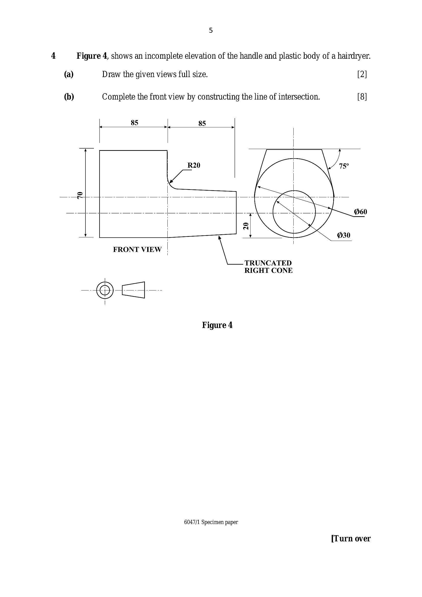
Figure 4, shows an incomplete elevation of the handle and plastic body of a hairdryer.(a) Draw the given views full size. [2]
(b) Complete the front view by constructing the line of intersection. [8]
a 85 >| 85 >|
R20
el :
[ne
|
¥ | !
FRONT VIEW | \
TRUNCATED
RIGHT CONE
|
Figure 4
6047/1 Specimen paper
[Turn over
---
Page 6
Extracted Text
5.(a)
6b)
©
SECTION B [60 Marks]
Answer any three questions.
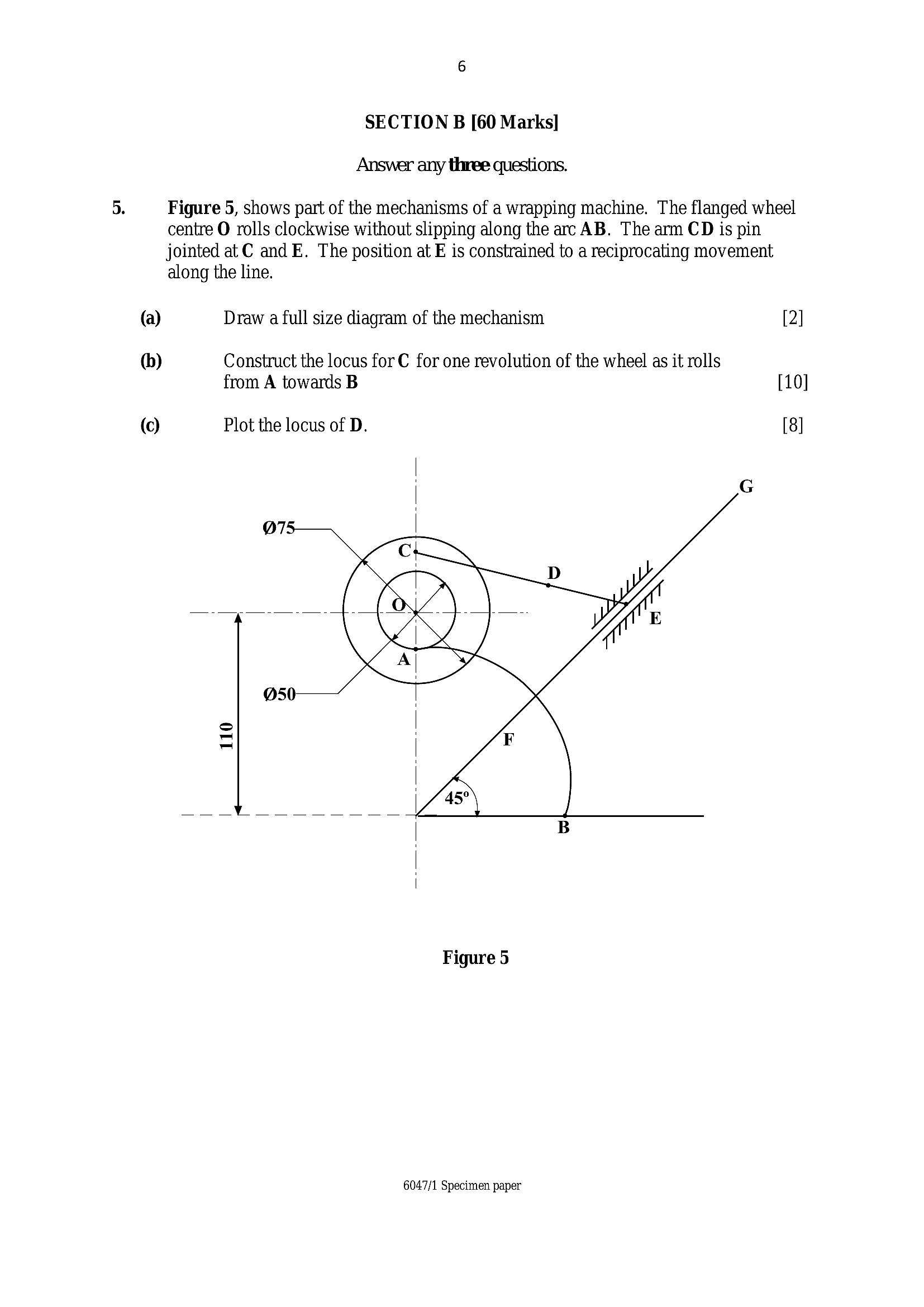
Figure 5, shows part of the mechanisms of a wrapping machine. The flanged wheel
centre O rolls clockwise without slipping along the arc AB. The arm CD is pin
jointed at C and E. The position at E is constrained to a reciprocating movement
along the line.
Draw a full size diagram of the mechanism [2]
Construct the locus forC for one revolution of the wheel as it rolls
from A towards B [10]
Plot the locus of D. [8]
110
Figure 5
6047/1 Specimen paper
---
Page 7
Extracted Text
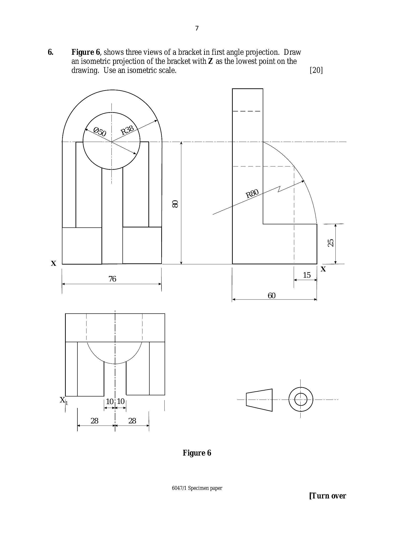
6. Figure 6, shows three views of a bracket in first angle projection. Draw an isometric projection of the bracket with Z as the lowest point on the drawing. Use an isometric scale. [20]Figure 6
6047/1 Specimen paper
[Turn over
---
Page 8
Extracted Text
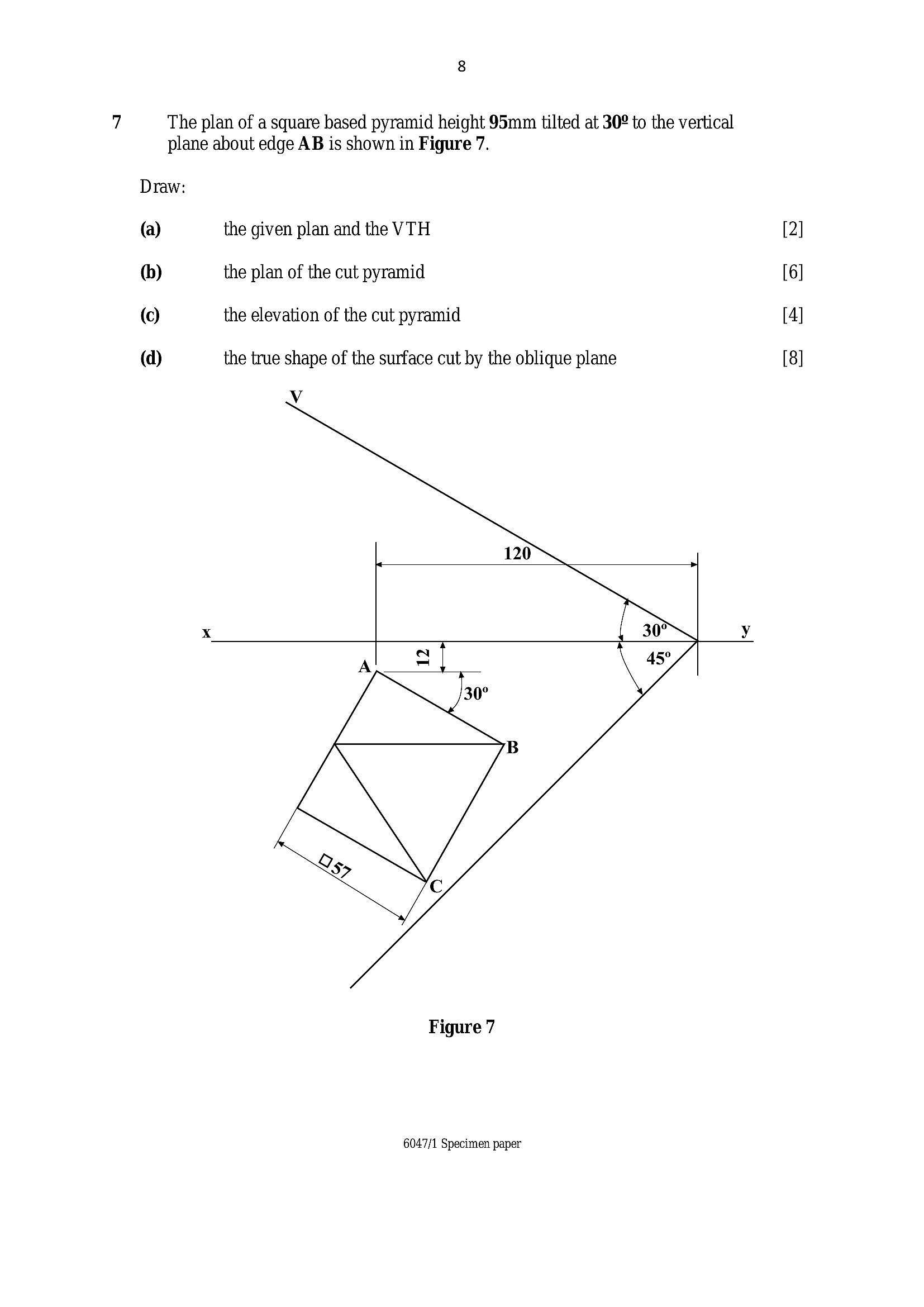
7The plan of a square based pyramid height 95mm tilted at 30° to the vertical
plane about edge AB is shown in Figure 7.
Draw:
(a)
(b)
©
Cc)
the given plan and the VTH
the plan of the cut pyramid
the elevation of the cut pyramid
the true shape of the surface cut by the oblique plane
Vv
Figure 7
6047/1 Specimen paper
---
Page 9
Extracted Text
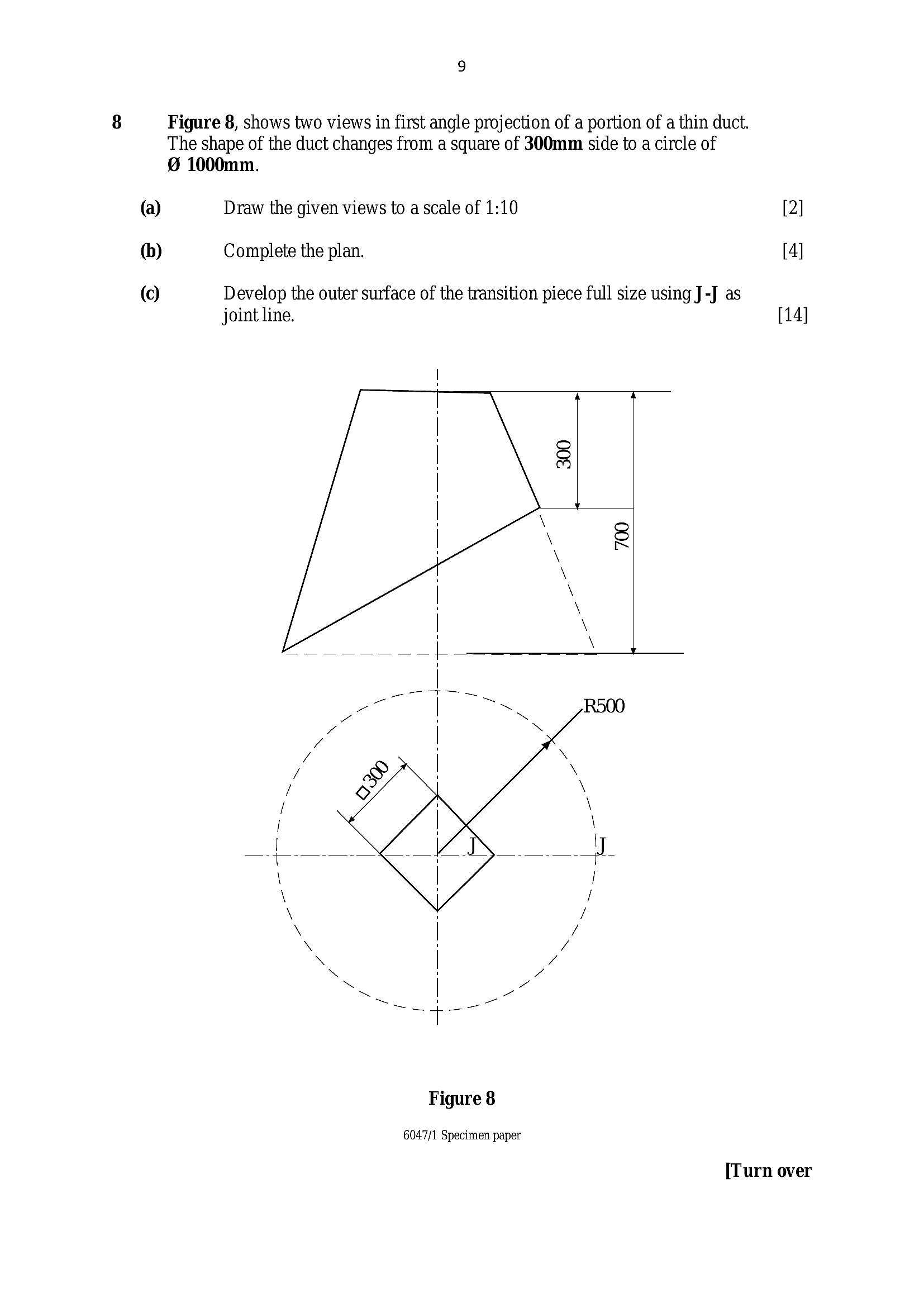
Figure 8, shows two views in first angle projection of a portion of a thin duct. The shape of the duct changes from a square of 300mm side to a circle of 8 1000mm.(a) Draw the given views to a scale of 1:10 [2]
(b) Complete the plan. [4]
(©) Develop the outer surface of the transition piece full size using J-J as
joint line. [14]
Figure 8
6047/1 Specimen paper
[Turn over
---
Page 10
Extracted Text
9.(a)
6b)
©
(d)
10
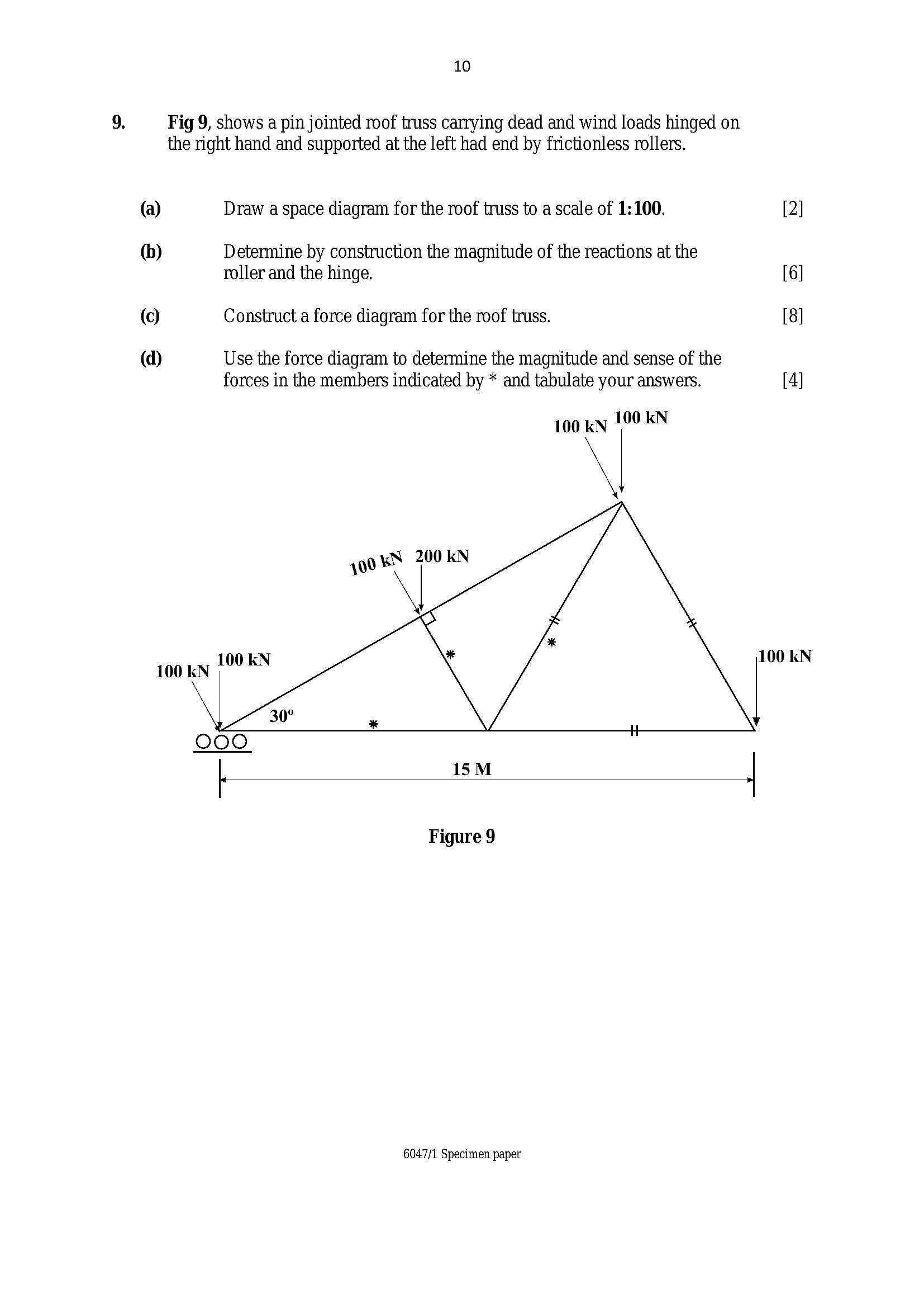
Fig 9, shows a pin jointed roof truss carrying dead and wind loads hinged on
the right hand and supported at the left had end by frictionless rollers.
Draw a space diagram for the roof truss to a scale of 1:100.
Determine by construction the magnitude of the reactions at the
roller and the hinge.
Construct a force diagram for the roof truss.
Use the force diagram to determine the magnitude and sense of the
forces in the members indicated by * and tabulate your answers.
100 kN 100 KN
\
} 15M
Figure 9
6047/1 Specimen paper
---
Page 11
Extracted Text
11BLANK PAGE
6047/1 Specimen paper
---
Page 12
Extracted Text
12BLANK PAGE
6047/1 Specimen paper
---