


📄 Exam Questions & Readable Text Transcript
Full OCR-extracted text of questions, syllabus codes, and exam instructions.
Extracted Content: 4055q01
Page 1
Extracted Text
Candidate Name Centre Number Candidate NumberBEC
ZIMBABWE SC HOOL EXAMINATIO NS COUNCIL
General Certificate of Education Ordinary L evel
METAL TECHNOLOGY AND DESIGN 4055/1
PAPER1 Theory, Drawing and Design
SPECIMEN PAPER
Additional materials:
Answer paper
Drawing paper A2 size (1 sheet)
Standard drawing equipment
TIME: 3 hours
INSTRUCTIONS TO CANDIDATES
Write your name, centre number and candidate number in the spaces provided on the top of every
paper used.
Section A: Structured questions.
Answer all questions.
Write your answers on the spaces provided.
Section B: Free response questions.
Answer two question only from the chosen option.
Write your answer on the separate answer paper provided.
Section C
Answer both questions 11(a) and 11(b).
Answer these questions on the A2 drawing paper provided.
At the end of the examination, fasten together your answer sheets to Sections A and B and place
them within your folded drawing paper for Section C.
INFORMATION FOR CANDIDATES
The number of marks is given in brackets [ ] at the end of each question or part question.
Y ou are advised to spend no longer than 45 minutes on Section A and no longer than 45 minutes
on Section B.
Except where pictorial views are used, all diagrams are in first angle projection.
This question paper consists of 13 printed pages and 3 blank pages.
Copyright: Zimbabwe School Examinations Council, Specimen paper.
©ZIMSEC Specimen paper [Turn over
---
Page 2
Extracted Text
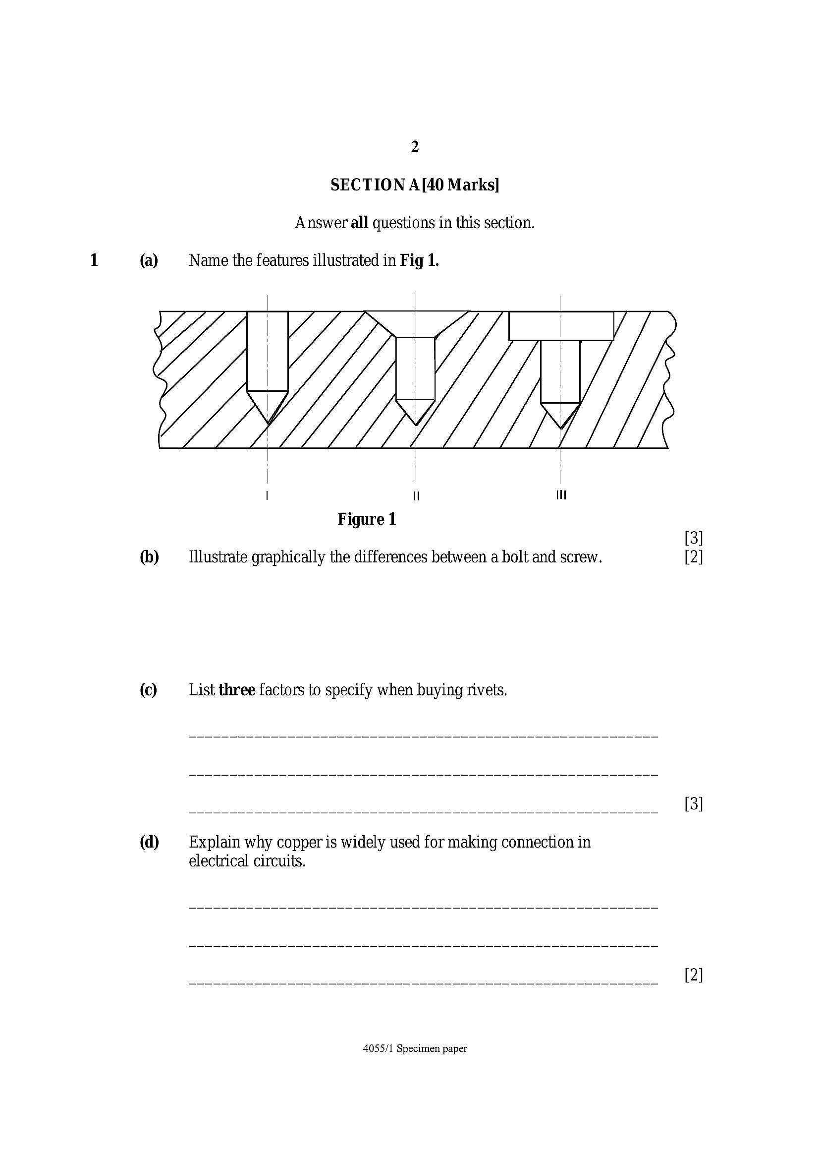
2 SECTION A[40 Marks] Answer all questions in this section.(a) Name the features illustrated in Fig 1.
Figure 1
(b) _ Illustrate graphically the differences between a bolt and screw. [2]
(©) List three factors to specify when buying rivets.
(d) —_‘ Explain why copper is widely used for making connection in
electrical circuits.
4055/1 Specimen paper
---
Page 3
Extracted Text
2 (a) Define the following terms:@ Brittleness
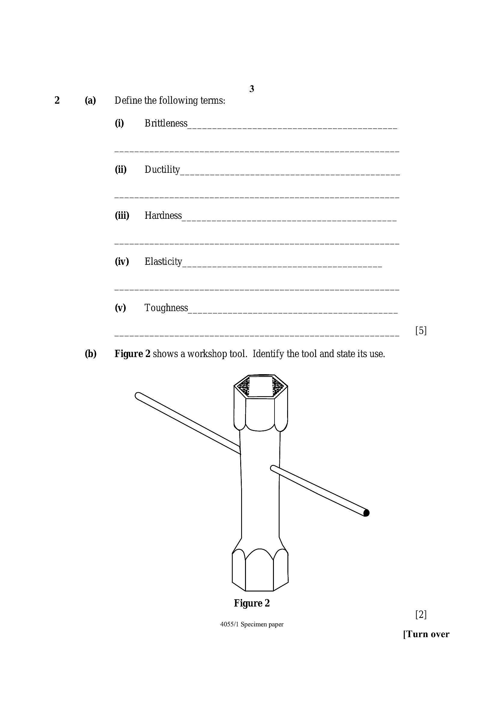
(b) Figure 2 shows a workshop tool. Identify the tool and state its use.
Figure 2
[2]
[Turn over
4055/1 Specimen paper
---
Page 4
Extracted Text
4 (©) High speed steel is an alloy containing 14-18% of tungsten.Name two tools that can be made out of this metal.
@ Give the meaning of B.D.M.A.S
(a) A sheet of iron is coated with Zinc.
@ Name the process
(ii) Givethereasonforthecoating
(b) Briefly explaintheuseofasolidmut
() Distinguish between High Carbon steel and mild steel.
4055/1 Specimen paper
---
Page 5
Extracted Text
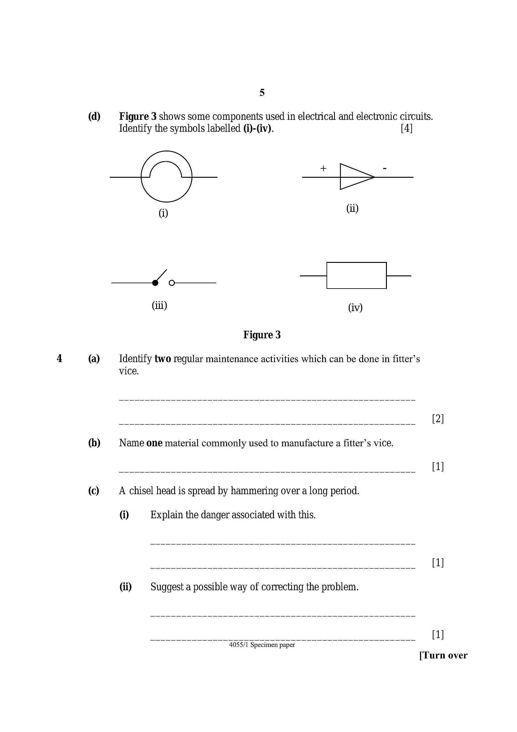
5@ Figure 3 shows some components used in electrical and electronic circuits.
Identify the symbols labelled (i)-(iv). [4]
a
i) Gi)
Jo sf
(iii) (iv)
Figure 3
(a) _—_ Identify two regular maintenance activities which can be done in fitter’s
vice.
(b) Name one material commonly used to manufacture a fitter’s vice.
(©) A chisel head is spread by hammering over a long period.
@ Explain the danger associated with this.
(ii) Suggest a possible way of correcting the problem.
[1]
[Turn over
4055/1 Specimen paper
---
Page 6
Extracted Text
(d)(e)
6
Y ou have planned to start a welding business at your local growth point.
State any three factors that you may consider important before you start
your business.
4055/1 Specimen paper
---
Page 7
Extracted Text
7 Section B Answer any two questions from this section on separate answer sheets provided.SHEET METAL/BEATEN METAL TECHNOLOGY
(a) Name the most appropriate tool for marking out lines on tinplate. [1]
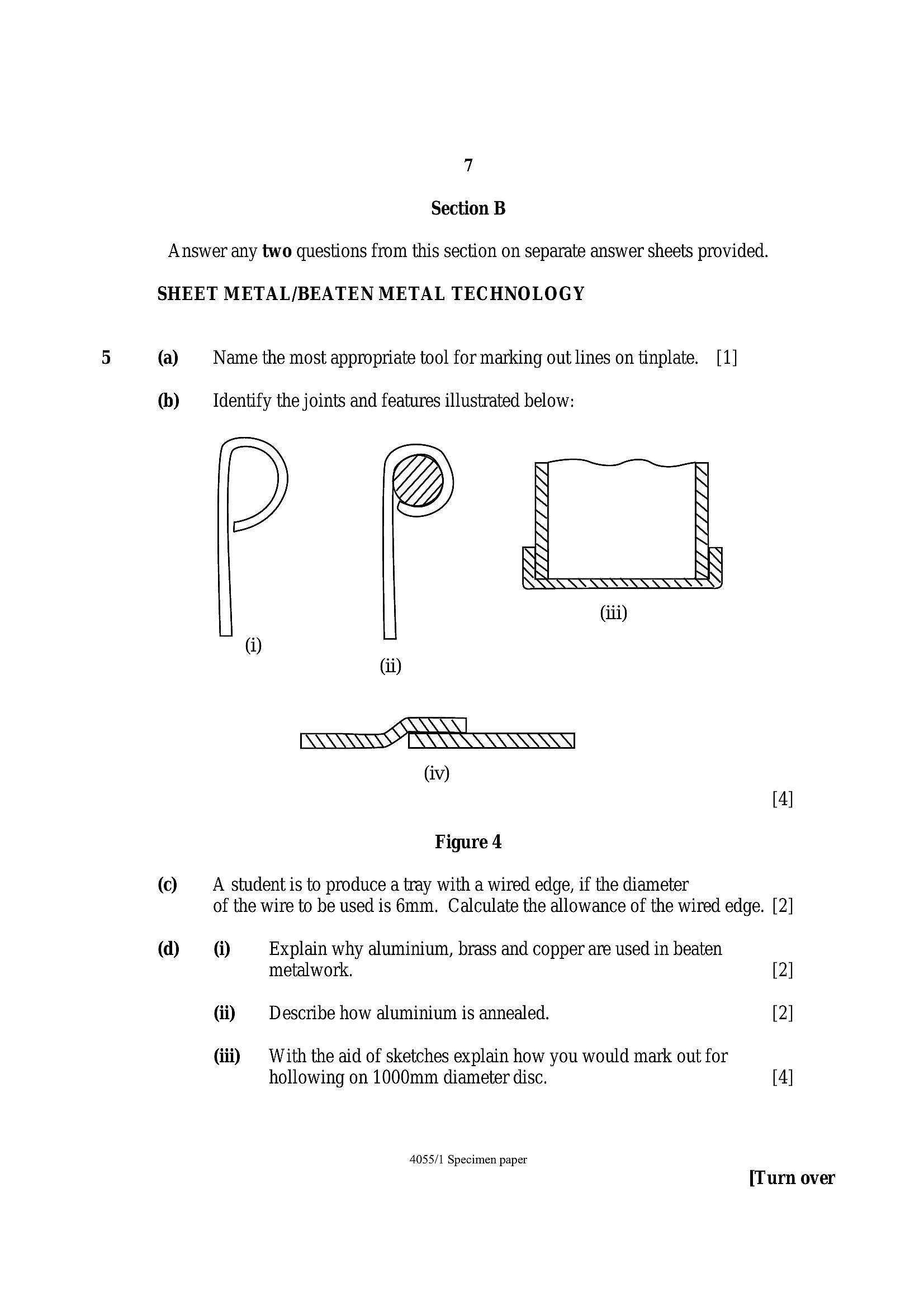
(b) Identify the joints and features illustrated below:
@
Gv)
[4]
Figure 4
(©) A student is to produce a tray with a wired edge, if the diameter
of the wire to be used is 6mm. Calculate the allowance of the wired edge. [2
@ @ Explain why aluminium, brass and copper are used in beaten
metalwork. 2
di Describe how aluminium is annealed. 2
(iii) © With the aid of sketches explain how you would mark out for
hollowing on 1000mm diameter disc. 4
4055/1 Specimen paper
[Turn over
---
Page 8
Extracted Text
FORGE/FOUNDRY TECHNOLOGY6
(a)
(b)
©
(d)
(e)
®
(a)
6b)
©
(d)
Name the correct fuel to use when forging.
On what portion of the anvil should chiselling be done?
Sketch the following forge tools:
@ Hardie,
di Flatter.
With the aid of sketches describe the process of forge welding.
With reference to casting, state the uses of the following furnaces:
@ Cupola,
(i) Crucible.
State the uses of the following casting equipment:
@ Spruce pins and risers,
di Rammer,
(ii) Crucible tong,
(iv) Spoon tool.
State the use of tongs.
Name a tong used to:
(1) pick up hot pieces of metal from the fire,
(ii) hold heavy square or rectangular sections,
(iii) hold thin metal sections.
Show in sketch form the use of top and bottom fullers.
State two safety precautions necessary when forging.
4055/1 Specimen paper
---
Page 9
Extracted Text
(a)6b)
©
(d)
(e)
9
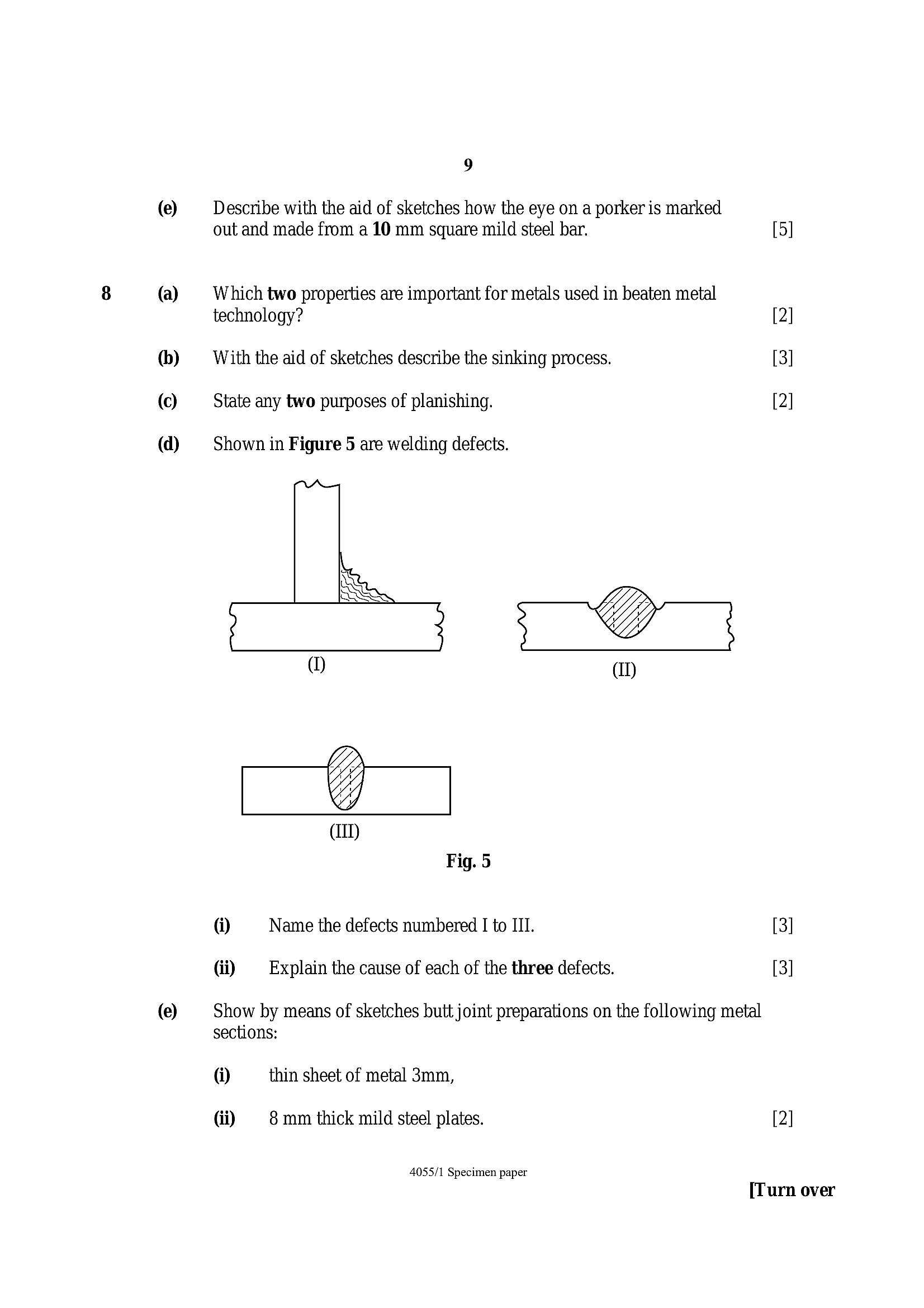
Describe with the aid of sketches how the eye on a porker is marked
out and made from a 10 mm square mild steel bar. 5
Which two properties are important for metals used in beaten metal
technology? 2
With the aid of sketches describe the sinking process. 3
State any two purposes of planishing. 2
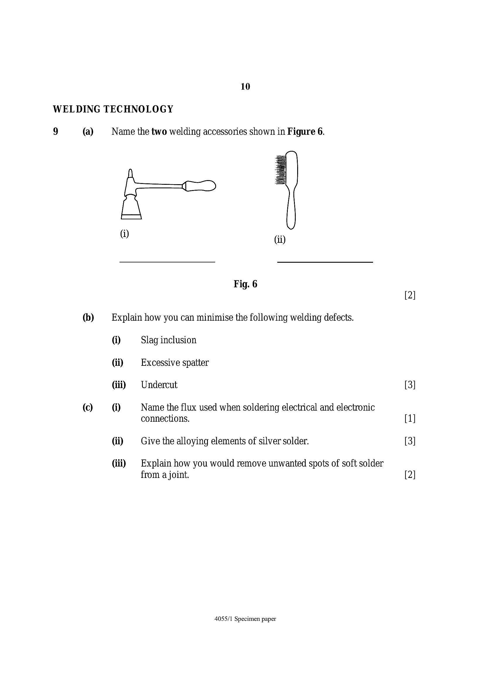
Shown in Figure 5 are welding defects.
a On
@) (I)
@ Name the defects numbered I to III. [3]
di Explain the cause of each of the three defects. [3]
Show by means of sketches butt joint preparations on the following metal
sections:
@ thin sheet of metal 3mm,
di 8 mm thick mild steel plates. [2]
4055/1 Specimen paper
[Turn over
---
Page 10
Extracted Text
10WELDING TECHNOLOGY
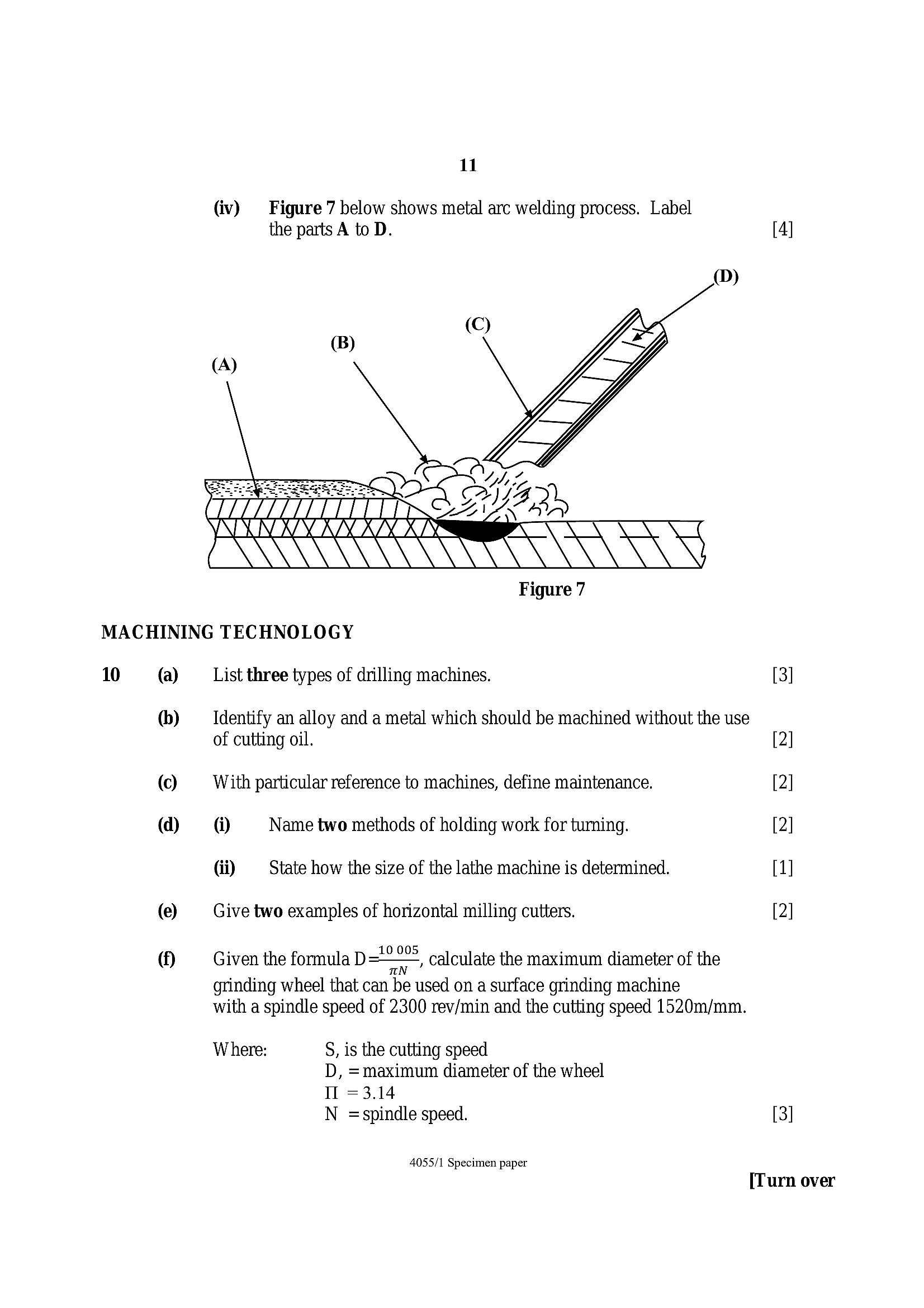
9 (a) Name the two welding accessories shown in Figure 6.
® (i)
Fig. 6
(b) Explain how you can minimise the following welding defects.
@ Slag inclusion
di Excessive spatter
Gii) = Undercut
(c) @ Name the flux used when soldering electrical and electronic
connections.
di Give the alloying elements of silver solder.
(ii) Explain how you would remove unwanted spots of soft solder
from a joint.
4055/1 Specimen paper
---
Page 11
Extracted Text
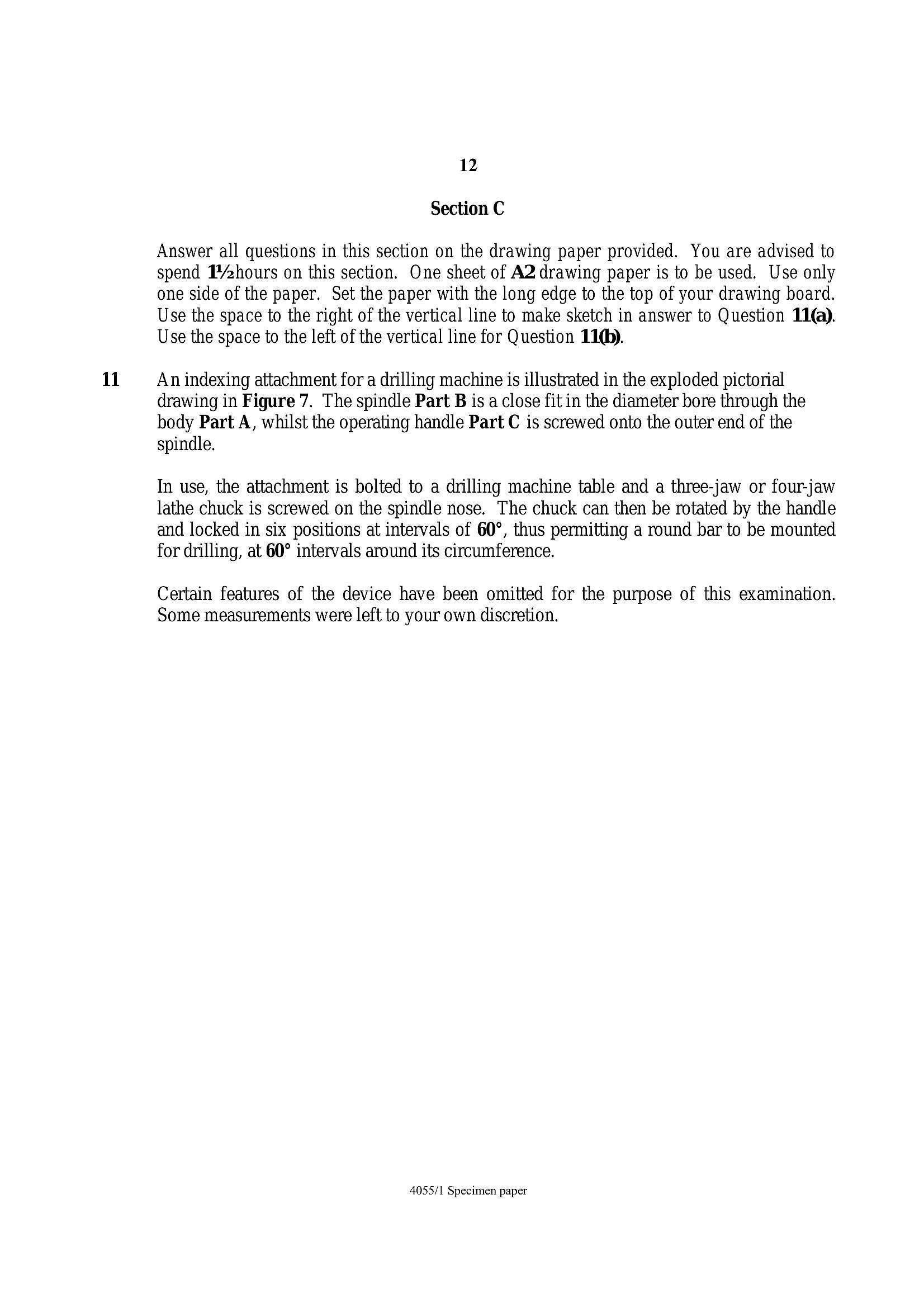
11(iv) _ Figure 7 below shows metal arc welding process. Label
the parts A to D. [4]
(D)
©
(B)
MACHINING TECHNOLOGY
10
(a)
6b)
©
(d)
(e)
(i)
List three types of drilling machines. 3
Identify an alloy and a metal which should be machined without the use
of cutting oil. 2
With particular reference to machines, define maintenance. 2
@ Name two methods of holding work for turning. 2
di State how the size of the lathe machine is determined. 1
Give two examples of horizontal milling cutters. 2
Given the formula D=~“° calculate the maximum diameter of the
grinding wheel that can be used on a surface grinding machine
with a spindle speed of 2300 rev/min and the cutting speed 1520m/mm.
Where: S, is the cutting speed
D, =maximum diameter of the wheel
Il =3.14
N =spindle speed. [3]
4055/1 Specimen paper
[Turn over
---
Page 12
Extracted Text
1112
Section C
Answer all questions in this section on the drawing paper provided. You are advised to
spend 1’hours on this section. One sheet of A2 drawing paper is to be used. Use only
one side of the paper. Set the paper with the long edge to the top of your drawing board.
Use the space to the right of the vertical line to make sketch in answer to Question 11).
Use the space to the left of the vertical line for Question 11®).
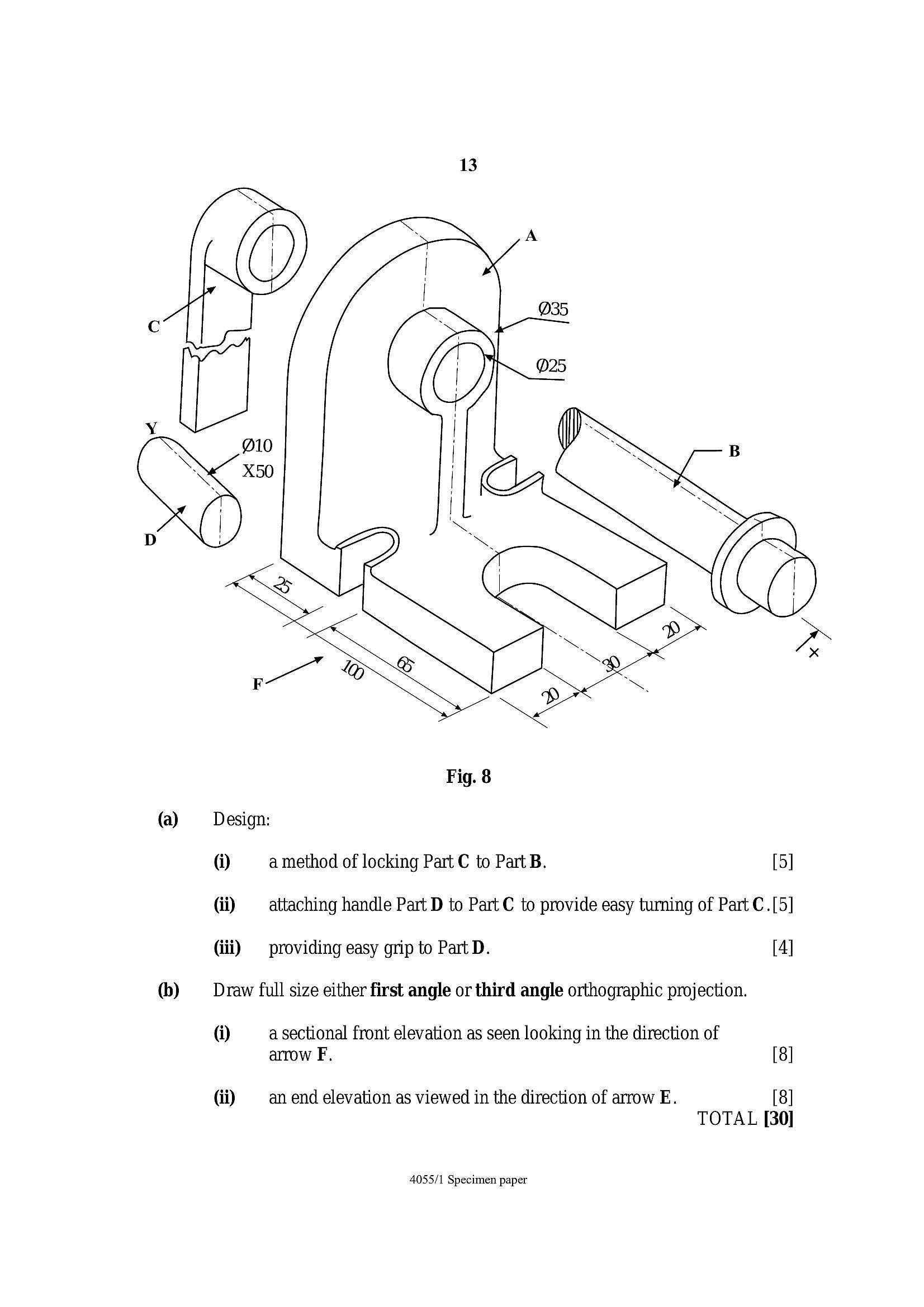
An indexing attachment for a drilling machine is illustrated in the exploded pictorial
drawing in Figure 7. The spindle Part B is a close fit in the diameter bore through the
body Part A, whilst the operating handle Part C is screwed onto the outer end of the
spindle.
In use, the attachment is bolted to a drilling machine table and a three-jaw or four-jaw
lathe chuck is screwed on the spindle nose. The chuck can then be rotated by the handle
and locked in six positions at intervals of 60°, thus permitting a round bar to be mounted
for drilling, at 60° intervals around its circumference.
Certain features of the device have been omitted for the purpose of this examination.
Some measurements were left to your own discretion.
4055/1 Specimen paper
---
Page 13
Extracted Text
vO(a)
(b)
13
Fig. 8
Design:
@ a method of locking Part C to Part B. [5]
(ii) attaching handle Part D to Part C to provide easy turning of Part C.[5]
(iii) providing easy grip to Part D. [4]
Draw full size either first angle or third angle orthographic projection.
@ a sectional front elevation as seen looking in the direction of
arrow F. [8]
di an end elevation as viewed in the direction of arrow E. [8]
TOTAL [30]
4055/1 Specimen paper
---
Page 14
Extracted Text
14 BLANK PAGE4055/1 Specimen paper
---
Page 15
Extracted Text
15 BLANK PAGE4055/1 Specimen paper
---
Page 16
Extracted Text
16 BLANK PAGE4055/1 Specimen paper
---